A tight 25–30 day window can be realistic for installing a veneer dryer machine only when the project is treated like a documentation-first job. In practice, most schedule overruns come from late changes—dimensions that don’t match the shop, foundations that need rework, utilities that aren’t ready, or a heat-source decision that shifts mid-assembly. For plywood veneer drying, those surprises are expensive because they ripple into feeding direction, material handling space, and commissioning time.
This article focuses on what to have confirmed before the installation countdown starts, using representative specifications and configurations from Shine Machinery’s Vertical Veneer Dryer and roller-type Veneer Drying System solutions.

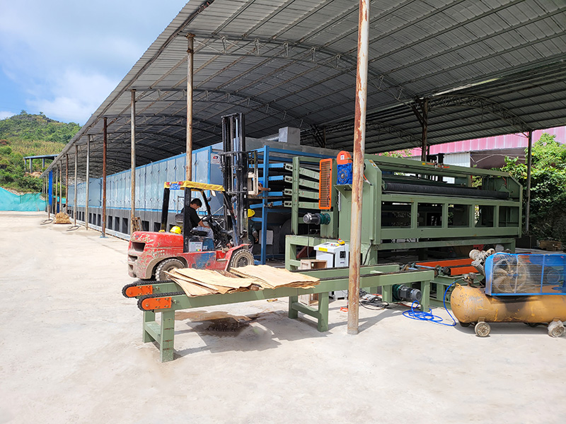
When a veneer dryer machine arrives on site, assembly is only one part of the work. The dryer must physically fit the workshop, align with the existing production flow, connect to a confirmed heat source, and meet target moisture requirements for Drying Veneer. If any of those inputs are still “to be decided,” teams end up improvising—moving anchor points, rerouting ducting, resizing foundations, or reworking power distribution.
For procurement teams, the goal is straightforward: reduce open questions to a controlled checklist, and lock the decisions that affect layout, utilities, and commissioning criteria.
A Veneer Drying System typically demands a small set of practical documents and confirmations. The exact format may vary by project, but the content should be clear enough that both the installer and the mill agree on what “ready” means.
At minimum, confirm:
Overall machine dimensions and installation position
Veneer infeed/outfeed direction (material movement)
Required operating and maintenance access space
This step becomes even more important when comparing compact Vertical Veneer Dryer layouts with longer roller-dryer lines.
Before the first day of installation work, confirm:
Foundation dimensions
Installation reference points (where the equipment sits)
Structural requirements at the installation area
A late foundation change rarely stays local—it can shift alignment, affect feeding/discharging space, and complicate utility routing.
Confirm the dryer’s installed power, plus connection requirements. For example, the 20m Automatic Veneer Dryer Machine (model GTH30-20) lists 145.5 kW total power and about 100 kWh per hour actual electricity consumption.
That distinction matters in planning: installed power affects upstream capacity and cabling selection, while hourly consumption is often used for operating cost expectations and energy planning.
Roller dryers in Shine Machinery’s lineup are commonly configured with multiple heat-source options, including biomass burner, steam, natural gas, and thermal oil.
Regardless of the option, what must be agreed early is:
The selected heat source (no “placeholder” choices)
The installation position of heating equipment
Required connections and space for operation
Changing heat source decisions after assembly starts tends to trigger mechanical changes and additional on-site coordination.
For plywood veneer drying, the project should define:
Veneer thickness range to be processed
Throughput requirement (capacity)
Final moisture target at discharge
These numbers shape commissioning criteria, line speed targets, and the operating window for drying temperature.
A fast installation plan is easier when the mill anchors its preparation to the chosen model’s parameters.
The GTH30-20 model parameters show how quickly requirements stack up:
Working width: 3.0 m
Decks: 4
Heating area length: 16 m
Cooling area length: 4 m
Veneer thickness: 0.6–8 mm
Drying temperature: 140–200°C adjustable (temperature control accuracy ±5°C)
Veneer transport speed: 5–22 m/min
Final moisture: fresh veneer to about 8–10%
Even without overcomplicating the engineering, these points define the minimum viable set of site readiness checks: footprint, power, heat interface, and production targets.
For mills planning higher daily capacity, the Plywood Veneer Machine (model GTH30-52) lists a covered space of 58 m × 9 m × 3 m, plus a 48 m heating area and 4 m cooling area.
Those dimensions make workshop layout approval non-negotiable. If the building constraints or conveying lanes are still unresolved, a 25–30 day install schedule becomes a gamble.
Many buyers compare a Vertical Veneer Dryer to a roller-type Low Cost Veneer Dryer when space, budget, or timeline is constrained. The key is to match the configuration to production goals rather than assuming any single design is “faster” to install.
Shine Machinery’s vertical dryer descriptions emphasize three-dimensional veneer loading and a countercurrent drying cycle, with equipment coverage described as only two-thirds of the area of a roller dryer.
A published example is the FBH30-13 model on the Vertical Veneer Dryer page:
Output: 2 m³/h
Size: 13 × 3 × 4 m
Total power: 15 kW
Fuel consumption: 200 kg/h
Moisture content: fresh veneer dried to 0–5%
Drying cost: reported as less than $8/m³
The same source also notes that this equipment needs to be assembled on the customer’s factory site, which makes early layout confirmation especially important.
The Low Cost Veneer Dryer is listed as a roller veneer dryer with:
Working width: 3 m
Veneer thickness: 0.8–8 mm
Heating area length: 32 m
Drying capacity: 50–60 m³/day
Heat source: biomass burner (other options available)
For time-critical installs, roller-type lines tend to raise more workshop routing questions simply because the line length, feeding area, and discharging area must fit cleanly into the broader plant flow.
Shine Machinery describes the dryer as organized into four functional sections: Feeding area, Heating area, Cooling area, and Discharging area. This is a practical way to structure layout discussions because each section maps to a different kind of site readiness check.

Feeding area: confirm infeed direction, handling approach, and operator space.
Heating area: confirm heating length, heat-source placement, and airflow/ducting interfaces.
Cooling area: confirm cooling length and downstream handling stability.
Discharging area: confirm transfer path to the next process step.
If any one of these areas is still ambiguous, installers typically compensate by leaving “temporary” gaps—which later turn into rework.
A compressed schedule works best as a sequence of locked gates.
Confirm model selection and major parameters
Approve layout and foundation requirements
Confirm electrical requirements and power readiness
Finalize heat-source choice and connection plan
Agree on final moisture target and throughput objective
Verify the installation area matches the approved arrangement
Confirm foundation readiness and access conditions
Begin assembly following the agreed installation instructions
Complete remaining assembly
Finish electrical connection work
Complete heating-system interfaces
Check feeding/discharging alignment with planned production flow
Commissioning should focus on performance targets tied to the chosen equipment. For roller dryers such as GTH30-20, operating parameters include adjustable 140–200°C drying temperature and 5–22 m/min conveying speed, with moisture targets listed as fresh veneer to about 8–10%.
The practical point is not the number of test hours—it’s agreeing in advance what “pass” looks like for moisture consistency and surface condition.
For buyers planning Drying Veneer capacity upgrades under tight time pressure, the most effective risk control is a final pre-start checklist:
Machine footprint and workshop routing are approved
Foundation dimensions and locations are confirmed
Installed power and electrical connection method are confirmed
Heat source is selected and positioned
Feeding direction and discharge integration are confirmed
Target moisture content and throughput requirement are defined
Commissioning criteria are agreed and measurable
If a mill also runs other roller-dryer configurations—such as the roller design described on the Roller Core Veneer Dryer Machine page, which emphasizes consistent moisture and flatness—those quality targets should be carried into commissioning so the new line starts stable, not just “powered on.”
Layout/positioning information, foundation requirements, electrical specifications, heat-source selection with connection interfaces, production parameters (thickness, capacity, moisture target), and installation instructions.
Examples include fresh veneer to about 8–10% for the GTH30-20 roller dryer and fresh veneer to 0–5% for the FBH30-13 vertical dryer.
Shine Machinery describes the Vertical Veneer Dryer coverage as only two-thirds of the area of a roller dryer, depending on configuration and site layout.
Published options include biomass burner, steam, natural gas, and thermal oil, depending on the selected configuration.
It can be planned around that window when the layout, foundation, power, heat-source decision, and commissioning targets are confirmed in advance and coordinated with site readiness.
Copyright By © Shandong Shine Machinery Co.,Ltd
 ไทย
ไทย Indonesia
 Melayu
 Tiếng Việt
 Pусский
 Portugues
 Français
 Deutsch
 日本語
日本語 한국어
한국어 العربية
 Italiano
 Polski
 Nederlands
 Türk dili
 हिन्दी
 Ελληνικά
 Svenska
 Español


